Parallel and Series Combination of Capacitor Project PDF Class 12

Introduction
Capacitors are pivotal components in electrical and electronic circuits, serving as crucial elements for energy storage and management. Their primary function is to store electrical energy in an electric field, which can then be released or regulated as needed within a circuit. The way capacitors are connected in a circuit can significantly influence their overall behaviour and effectiveness. This project focuses on exploring two fundamental configurations of capacitors: series and parallel combinations.
In a series combination, capacitors are arranged end-to-end, meaning the positive terminal of one capacitor is connected to the negative terminal of the next. This arrangement impacts the total capacitance of the circuit in a unique manner. The combined effect is such that the total capacitance is less than any individual capacitor in the series. This is because the total capacitance in a series arrangement is given by the reciprocal of the sum of the reciprocals of the individual capacitances. Thus, adding more capacitors in series results in a lower total capacitance.
Conversely, in a parallel combination, capacitors are connected such that all their positive terminals are linked together, and all their negative terminals are connected as well. In this configuration, the total capacitance is simply the sum of the individual capacitances. This means that connecting capacitors in parallel increases the total capacitance, as each capacitor contributes to the overall charge storage capacity of the circuit.
Aim
To verify laws of series and parallel combination of capacitors.
Material Required
- Capacitors (470 uF )
- Multi-meter
- Soldering iron
- Wire piece
THEORY
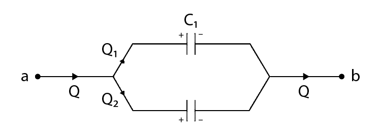
- Parallel Combination of Capacitors:
When capacitors are connected in parallel, the potential difference V across each is the same and the charge on C1 and C2 is different, i.e., Q1 and Q2.

The total charge in Q is given as:
The equivalent capacitance between a and b is:
C = C1 + C2
The charges on capacitors are given as:
- Q1=C1C1+C2Q
- Q2=C2C1+C2Q
In case of more than two capacitors, C = C1 + C2 + C3 + C4 + C5 + …………
- Series Combination of Capacitors:

Procedure
- Take 6 identical capacitors, measure capacitance of these capacitors by multi-meter.
- We have to connect the first 3 capacitors in parallel (circuit-1) and another 3 in series(circuit-2).
- We can connect the capacitors by the use of soldering iron, capacitors can be connected by putting the melted wire pieces over the connections with the help of soldering iron.
- Once the capacitors are connected, leave the circuit as it takes a few seconds for it to become solid at all its ends.
- Take a digital multi-meter and connect it across the terminals of the prepared Circuit-1 and Circuit-2.
- Set the multi-meter over the capacitance option so as to obtain the value of the associated capacitance of the circuit.
- Keep the multi-meter at same terminals for a while so that précised value of capacitance can be observed.
- Once value of capacitance obtained on multi-meter, compare it with the theoretically calculated value.
Calculation
Observation
Combination of Capacitor | Experimental Value of Capacitance | Theoretical Value of Capacitance |
Parallel | 1413.5 uF | 1410 uF |
Series | 153.2 uF | 156.66 uF |
Result
Capacitance in Parallel Cs=153.2 μF
Capacitance in Series Cp=1413.5 μF
Conclusion
The project successfully validated the theoretical laws of capacitor combinations. For the parallel configuration, the theoretical capacitance of 1410 μF closely matched the experimental value of 1413.5 μF, confirming that Cp= C1 + C2+ C3 is accurate. In the series configuration, the theoretical capacitance of 156.66 μF was near the experimental value of 153.2 μF, validating the formula
1/Cs = 1/C1 +1/C2 +1/C3 .
Minor differences between theoretical and experimental values are attributed to measurement inaccuracies and component tolerances. Overall, the results support the accuracy of the capacitor combination laws in practical applications.
Precautions
- Make sure all connections are neat and tight to avoid measurement errors.
- Set the soldering iron to an appropriate temperature to prevent damage to components.
- Ensure solder joints are clean and solid to avoid loose connections.
- Keep multi-meter probes clean and in good condition to prevent faulty readings.
- Double-check circuit arrangements to ensure correct series or parallel configurations.
- Avoid overheating capacitors during soldering to prevent performance degradation.
- Calibrate the multi-meter before starting the experiment to avoid systematic errors.
- Record all readings and observations carefully for accurate comparison with theoretical values.

