AC Generator Physics Investigatory Project PDF
[PDF Download link Given Below]
To get the link Scroll down to bottom of this Article
INTRODUCTION
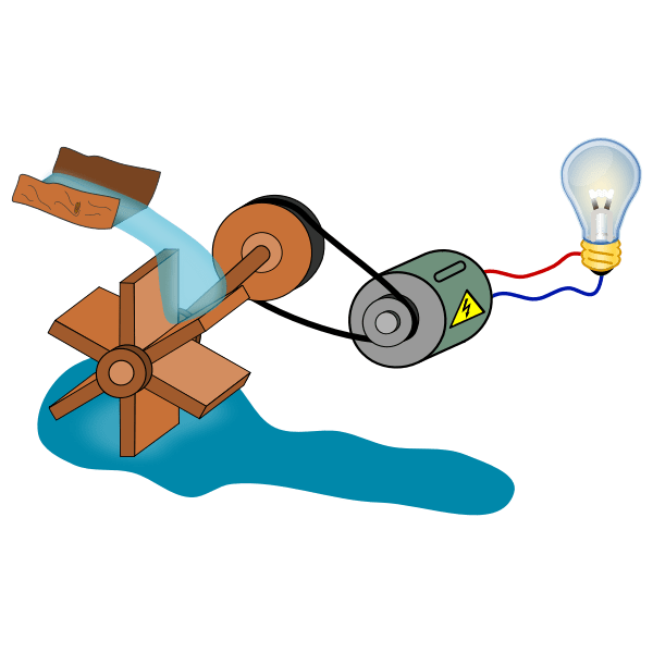
- An electric generator is a device that converts mechanical energy to electrical energy.
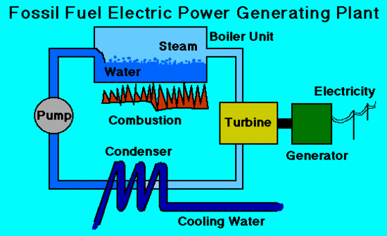
- A generator forces electric current to flow through an external circuit. The source of mechanical energy may be a reciprocating or turbine steam engine, water falling through a turbine or waterwheel, an internal combustion engine, a wind turbine, a hand crank, compressed air, or any other source of mechanical energy.
- Generators provide nearly all of the power for electric power grids.
THEORY AND WORKING
- The strong magnetic field is produced by a current flow through the field coil of the rotor.
- The field coil in the rotor receives excitation through the use of slip rings and brushes.
- Two brushes are spring-held in contact with the slip rings to provide the continuous connection between the field coil and the external excitation circuit.
- The armature is contained within the windings of the stator and is connected to the output.
- Each time the rotor makes one complete revolution, one complete cycle of AC is developed.
- A generator has many turns of wire wound into the slots of the rotor.
- The magnitude of AC voltage generated by an AC generator is dependent on the field strength and speed of the rotor.
- Most generators are operated at a constant speed; therefore, the generated voltage depends on field excitation, or strength.
Components of an AC Generator
FIELD
- The field in an AC generator consists of coils of conductors within the generator that receive a voltage from a source (called excitation) and produce a magnetic flux.
- The magnetic flux in the field cuts the armature to produce a voltage. This voltage is ultimately the output voltage of the AC generator.
ARMATURE
- The armature is the part of an AC generator in which voltage is produced.
- This component consists of many coils of wire that are large enough.
PRIME MOVER
-
The prime mover is the component that is used to drive the AC generator.
- The prime mover may be any type of rotating machine, such as a diesel engine, a steam turbine, or a motor.
ROTOR
- The rotor is driven by the generator’s prime mover, which may be a steam turbine, gas turbine, or diesel engine. Depending on the type of generator, this component may be the armature or the field.
- The rotor will be the armature if the voltage output is generated there; the rotor will be the field if the field excitation is applied there.
STATOR
- Like the rotor, this component may be the armature or the field, depending on the type of generator.
The stator will be the armature if the voltage output is generated there; the stator will be the field if the field excitation is applied there
-
The stator of an AC generator is the part that is stationary.
-
The rotor of an AC generator is the rotating component of the generator, as shown in Figure 1.
SLIP RINGS
-
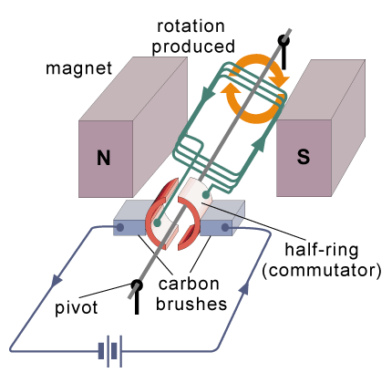
In a DC generator, a commutator was used to provide an output whose current always flowed in the positive direction.
-
Slip rings are used in AC generators because the desired output of the generator is a sine wave.
-
The slip ring consists of a circular conducting material that is connected to the rotor windings and insulated from the shaft. Brushes ride on the slip ring as the rotor rotates. The electrical connection to the rotor is made by connections to the brushes.
-
Slip rings are electrical connections that are used to transfer power to and from the rotor of an AC generator.

EFFICIENCY
- Efficiency of an AC generator is the ratio of the useful power output to the total power input.
- Because any mechanical process experiences some losses, no AC generators can be 100 per cent efficient.
- Efficiency of an AC generator can be calculated using Equation.
- Efficiency = [Output /Input] X 100
OR
Efficiency = [POWER OUT/POWER IN] X 100
EFFICIENCY OF ELECTRIC GENERATOR
|
POWER= VOLTAGE X CURRENT |
|
EFFICIENCY = [POWER OUTPUT / POWER INPUT ] 100 |
RESULT
- WHEN THE AXLE OF GENERATING MOTOR IS ROTATED, E.M.F. IS PRODUCED BY IT.
REASON: CHANGE IN FLUX THROUGH THE WINDING OF MOTOR.
- THIS E.M.F. REMAINS IN THE CIRCUIT AS LONG AS AXLE IS ROTATED.
HENCE, FARADAY’S LAW OF ELECTROMAGNETIC INDUCTION IS VERIFIED.
- AS THE SPEED OF ROTOR IS INCREASED, THE VOLTAGE AND CURRENT PRODUCED BY GENERATOR ALSO GET INCREASED.
REASON: RATE OF CHANGE OF FLUX INCREASES.
USES
- Aircraft auxiliary power generation, wind generators, high speed gas turbine generators.
- Hybrid electric vehicle (HEV) drive systems, automotive starter generators.
- An ac generator, or ‘alternator’, is used to produce ac voltages for transmission via the grid system or, locally, as portable generators.
- All of our household appliances run on ac current. Ex: Refrigerator, washing machines, oven, lights, fan etc.

LOSSES IN AC GENERATOR
Internal Voltage Drop
- The load current flows through the armature in all AC generators. The armature has some amount of resistance and inductive reactance.
- The combination of these make up what is known as the internal resistance, which causes a loss in a n AC generator.
- When the load current flows, a voltage drop is developed across the internal resistance.
This voltage drop subtracts from the output voltage and, therefore, represents generated voltage and power that is lost and not available to the load.
HYSTERESIS LOSSES
- Hysteresis losses occur when iron cores in an AC generator are subject to effects from a magnetic field.
- The magnetic domains of the cores are held in alignment with the field in varying numbers, dependent upon field strength.
- The magnetic domains rotate, with respect to the domains not held in alignment, one complete turn during each rotation of the rotor. This rotation of magnetic domains in the iron causes friction and heat.
- The heat produced by this friction is called magnetic hysteresis loss.
- After the heat-treated silicon steel is formed to the desired shape, the laminations are heated to a dull red and then allowed to cool.
- This process, known as annealing, reduces hysteresis losses to a very low value.
- To reduce hysteresis losses, most AC armatures are constructed of heat-treated silicon steel, which has an inherently low hysteresis loss.
MECHANICAL LOSSES - Rotational or mechanical losses can be caused by bearing friction, brush friction on the commutator, and air friction (called windage), which is caused by the air turbulence due to armature rotation.
- Careful maintenance can be instrumental in keeping bearing friction to a minimum.
- Clean bearings and proper lubrication are essential to the reduction of bearing friction.
- Brush friction is reduced by ensuring: proper brush seating, proper brush use, and maintenance of proper brush tension.
- A smooth and clean commutator also aids in the reduction of brush friction
PRECAUTIONS
- Do all the connection carefully
- Fix all the component on cardboard with strong glue
- Do not take a high voltage LED bulb (1.5V preferred)
- Use only DC motor in making the model
- Before doing any experiment please consult to your subject teacher or lab assistance
BIBLIOGRAPHY
- Wikipedia.com
- Google search engine
- Physics NCERT book
AC Generator Physics Investigatory Project PDF Download Link

